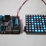
Serial 8×8 RGB LED Matrix Module for Arduino
The RGB LED matrix module is driven with serial data interface. It can be attached to any devices including Arduino via I2C and works as a I2C slave device, or via serial UART (can be attached to PC via a USB-TTL adapter). The module has 5×8 character font built in as well as 3×5 and 3×7 digit font, so that numbers and letters can be displayed in color easily. The module is powered by 5V input and has a 6-pin connector providing SDA, SCL, GND, VCC, RxD, TxD breakout.
An Arduino library has been developed on GitHub, where you can also find a example code demostrating the use of the library. All you need to do is to place the library header file in your sketch folder. For older version (ordered in 2012), please download the library here.
The following is a simple example sketch demostrating features of the library:
#include <Arduino.h>
#include <Wire.h>
#include "RGBMatrix.h"

#define I2C_ADDR 0x62

CFrameBuffer fb;
CRGBMatrixI2C matrix;

void setup()
{
    // initialize matrix module at default I2C address
    matrix.Init(I2C_ADDR);

    // clear screen
    matrix.Clear();

    // render by setting pixel directly
    for (byte y = 0; y < 8; y++) {
        for (byte x = 0; x < 8; x++) {
            matrix.SetPixel(x, y, 31 + y * 32, 0, 0);
            matrix.Draw();
            delay(50);
        }
    }
    delay(1000);

    // render by setting pixel in local frame buffer
    fb.Clear();
    for (byte y = 0; y < 8; y++) {
        for (byte x = 0; x < 8; x++) {
            fb.SetPixel(x, y, 0, 31 + y * 32, 0);
            matrix.SetFrame(fb);
            delay(50);
        }
    }
    delay(1000);
}

void loop()
{
    matrix.Clear();
    for (byte c = '0'; c <= '9'; c++) {
        matrix.ShowChar5x7(c, 2, -1, 0, 128, 255);
        matrix.Draw();
        delay(250);
    }

    for (byte n = 0; n <= 99; n++) {
        matrix.Clear();
        matrix.ShowDigit3x5(n / 10, 0, 0, 0, 255, 255);
        matrix.ShowDigit3x5(n % 10, 4, 0, 0, 255, 255);
        matrix.Draw();
        delay(100);
    }
}
The demo video shows the RGB matrix working with an Arduino UNO. A bit blinky in the video as the LEDs are driven with PWM.


