 Today I tried making something with the Arduino RGB LED matrix and adapter shield on hand. The idea is to let the pixels of the matrix change in correspondent to the change of car’s engine RPM (or some other realtime data, maybe throttle position) and a step forward is to display a digit in different colors. The digit can even be displayed mirrored so the matrix can be put on the dashboard and reflect the digit on the window shield.
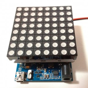
This is what the RGB LED matrix is like when stacked on an Arduino board. It is attached to an Arduino board through an adapter shield. Every pixel of the RGB LED matrix has 3 LED elements of red, green and blue whose brightness can be adjusted via PWM respectively. The shape of pixel is available as round dot and square dot at different costs.
With the example code provided with the shield, it’s really easy to get the matrix lit up and show some characters.
It doesn’t take me so much time to light up the RGB matrix and display some characters. With the data obtained from OBD-II with OBD-II Adapter for Arduino , a fancy digital tachometer is done easily.
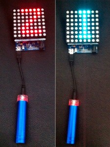
Now I got this on my car (see the video). The number displayed reflects the engine RPM or engine load percentage (e.g. 3 for 30%, 9 for 90%+). The color is also changed with the change of engine RPM (e.g. turning red after 6000rpm).
Some demostration videos:


